"Specialists in American Flyer Trains & S-Gauge Railroading"
888-708-0782 (from US only)
978-465-8798 (International)
Phone calls: 2-5 PM Eastern
Time, Tue-Thu only

AM. FLYER REPAIR CLINICS
CLINIC # 30: Building & Installing a S Scale Closed Frog Switch
Building & Installing a S Scale Closed Frog Switch
All of the attached documentation is based on how I installed my closed frog switches. In most cases you can use the techniques described even if you are not installing under similar conditions, Enjoy.
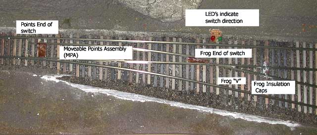
Figure 1: Shows a competed switch: Points are located below the text, MPA is the complete assembly in the middle (2 rails and 3 plates), Frog end is located below the text, frog “V” is located above the text and Frog insulation caps are located on the 2 rails above the text.
Assumptions:
- American Models Flex track is used for main line and long stretches of sidings.
- Switches will be built in place, with hand laid track to connect to the AM flex as required.
- Tortoise Switch motors are used to power switches.
- Power routing is accomplished using contacts on Tortoise switch motors.
- Major steps in building/installing switch: install sub-roadbed, install roadbed, install ties, build switch, install switch motor, test final corrections and enjoy!
- Code 148 rail is used.
Materials list:
- Micro Engineering code 148 rails.
- American Models 148 flex track.
- Wood ties. You need both standard length and switch length. Make sure they are the same thickness, and idea would be that they match the AM plastic ties. You need about 10 standard ties and 50 switch ties per number 5 switches. About 44 standard ties per foot for hand laid track.
- Spikes: We are using 3/8” medium spikes from Micro Engineering. You need about 250 per switch. Buy plenty!
- Brass sheet, .010” stock, about 2” x 1” per switch
- Brass tube, .032” ID, 3” per switch
- Brass rod, .032” OD, 4” per switch
- Wire to power frog and movable points assembly. We used 18-gauge multi strand.
- Electrical solder.
Tools:
- Needle-nosed pliers used to push in spikes.
- Wire strippers, screwdrivers, rail cutter and general working on your layout tools.
- Resistance soldering iron (you can actually build your own, I did - see project plans at: http://www.trainweb.org/bristol-s-gauge/Projects/rsu.html)
- 2 or 3 3-point track gauges for code 148
- NASG track gauge for fine tuning.
- Assortment of files and sandpaper
Install sub-roadbed
- Identify where you want to lay your switch.
- Depending on your sub-roadbed design you need to make sure that you have a clean, flat, smooth surface to lay roadbed. Sub-roadbed is often created using plywood or homosote. For example if you are using L-girder design you need to do the following.
- Locate where sub-roadbed is to be placed
- Temporarily align sub-roadbed (with risers using clamps if you are using L-girder railroad construction design).
- Level sub-roadbed and secure with screws. Avoid using glue, in case you need to relocate the switch.
Install roadbed
- Roadbed is often purchased in cork strips or homosote such as Homabed.
- Locate where roadbed is to be place on sub-roadbed. Use a piece of rail to define the natural curve of the tracks turnout (from mainline to spur).
- Lay the two outer sections of the roadbed.
- Glue in place with Elmer's wood glue, or equivalent. Pin using pushpins to hold in place while glue is drying.
- Cut inner portion of roadbed to match the switch footprint and to align the outgoing track section.
- Glue in place with Elmer's wood glue, or equivalent. Pin using pushpins to hold in place while glue is drying.
- Once glue is cured remove the pushpins and sand flat to ensure a flat surface for ties.
Install ties
- Identify location of switch; this should already be defined based on the sub-roadbed.
- Mark off 3 or more inches of track section before and after the switch. This will be used for a portion of the hand laid rail to align to existing flex track or other track. Also this is where the ties will be laid.
- Identify the entrance and exit of the switch. Between these points is where you will install the switch ties, vs the standard rail ties. The entrance is where the points will be located. The exit is the point where the diverging tracks are far enough apart to allow 2 separate ties, instead of one long one.
- Install a thin film of Elmer's wood glue (or equivalent) over the area where the ties are to be located.
- Install small (standard size) ties up to the entrance of the switch.
- Install larger (switch ties) form the entrance of the switch to until about 2 inches past where the frog will be located.
- Install small (standard size) ties from the end where you just installed the switch ties out a few more inches. This design is based on mating flex track to hand laid switches.
- Place flat object on top of ties (add weight) and let cure.
- Once glue is cured, sand wood ties flat to ensure a good surface for laying rails. At this point the wood ties should be the same thickness as the AM ties.
- Much grief is caused by not having the ties under the switch flat. Use a straightedge to be sure they are all the same height.
Build Switch
- Identify location of outer straight rail. (This could also be done on a curved section of track just as easy)
- Spike in outer straight rail, this will be temporary. . Spike about every eight ties. Spike both sides of the rail on the same tie, don't alternate. Don't push the spikes down super tight at this point; as you will need to slide the rail in and out a couple of times before you are done.
- Identify location of outer curved rail.
- Spike in outer curved rail: gauge beginning at the points end. The outer straight and outer curved need to be in gauge for at least 3 inches before the points, more is better, this will be temporary.
- Identify the location on the entrance of the switch where the tracks become wider than the gauge, this is where the points of the switch will be located. Make both straight and curved rail sections. (Is this where the Inner switch rails get created? Both outer straight and curved rail sections are spiked by now.)
- File a notch in the rail, located on the train side of each rail that will allow for the switch rail to blend into the stationary rail. The notch should be filed down to the web of the rail at the point position. This should taper off, (typical 2” to 4” long) depending on the switch design, to allow for the switching rails to mate up smoothly to the stationary rail to allow for correct gauging of the rail. (Note if it is not perfect, one could remove the rail later on, once the switch rail is built, to make a final adjustment.) This happens a lot on the first couple of switches you make.
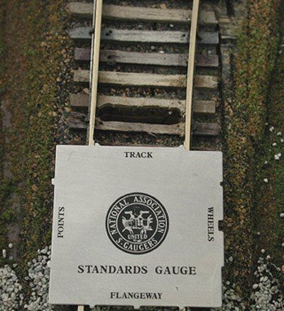
Figure 2: Shows the NASG track gauge where the rails start to separate. This is where you notch the rails for the points to contact. As you can see the rails are already notched.
7. Secure both inner straight and curve rail sections
8. Identify location of straight rail to frog
9. File down the frog end of the rail (take down ½ of the web) to a sharp knife-edge where the non-train side of the rail is flat. This should angled back, typical 1” to 3” in length.
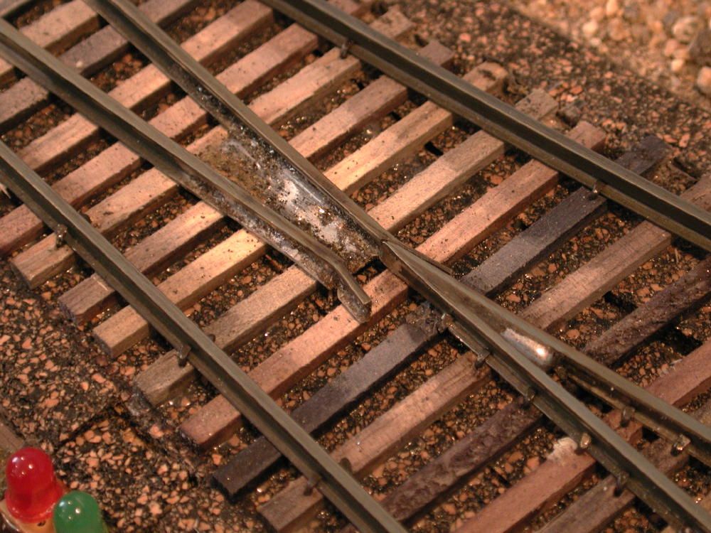
Figure 3: Here is a closed frog. Notice the thickness of the frog and the notch in the MPA need to be the same for a smooth transition.
10. File the train side of the rail flat at the point about 1/2” (take down the bottom side of the rail to allow for the switch rail to mate up to the frog rail smoothly) and taper back on the top side of the rail 1” to 3”.
11. Gauge and Spike in place the straight rail/frog, this will be temporary. This section of rail will be slid towards the switch entrance to align with the other half of the frog.
12. Identify location of curved rail to frog
13. File down the frog end of the rail (take down ½ of the web) to a sharp knife-edge where the non-train side of the rail is flat. This should angled back, typical 1” to 3” in length.
14. File the train side (same as step 10 on the other ½ of the points) of the rail flat at the point about 1/2” (take down the bottom side of the rail to allow for the switch rail to mate up to the frog rail smoothly) and taper back on the top side of the rail 1” to 3”.
15. Gauge and Spike in place the curved rail/frog, this will be temporary. This section of rail will be slid towards the switch entrance to align with the other half of the frog. Slide both curved rail/frog and straight rail/frog until the meet at a point where the gauge tool gaps the rail to the standard gap. You may still have to file down more material to get a nice point and even flow of the rail.
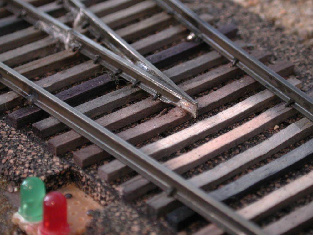
Figure 4: Shows a competed frog. Notice the rails are filed to a point and the lower part of the rail is notched. When the frog is soldered it should be a sharp point for a smooth transition. You can also see that the frog rails are isolated. I used thin plastic and Zap glue.
16. Once frog rails are located, spike rail in place, don't spike the first ½” to ¾” area of “V” but do spike every tie after that 2” to 3” down the rail. Eventually the rail will be cut to avoid power shorts.
17. Drill hole as close to “V” point as possible, through roadbed and sub-road bed for wire.
18. Strip and insert wire leaving a 1” non-insulated portion close to the “V” so you can solder this wire to the frog “V” point which will provide power to the switch.
19. Solder connecting rails in place with wire connected and hanging below the sub-roadbed.
20. Cut a section of rail to fit between the point location and about 1 inch past the frog, straight section first (this will be used to build part of the movable points assembly).
21. On one end of the rail you just cut file down the rail to a point where the rail blends with the point section of the switch (make sure you file down the correct side of the rail.
22. Notch the opposite end of the rail (outward towards the curved side) at the point where it will mate with the frog, then bend the end outward toward the curved side.
23. File down flat the end that is bent in so it will mate the frog with a smooth transition. This should also be aligned at the point end. This should complete that rail section for now.
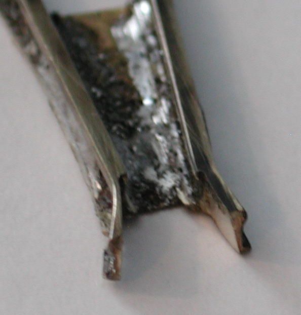
Figure 5: Here is a completed frog end of the MPA. Notice the bend and notch of the rails.
24. Cut a section of rail to fit between the point location and about 1 inch past the frog, now working on the curved section of the switch
25. Bend the rail so that in matcher the same curves formation as the switch.
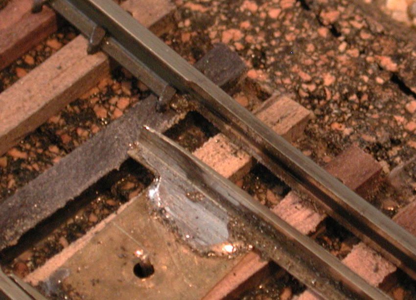
Figure 6: Shows the notch of the rails as well as the point's end of the Moveable Point Assembly (MPA). Notice the thickness of the notch and the thickness of the points.
26. File down the rail to a point where the rail blends with the point section of the switch.
27. Notch the opposite end of the rail (outward towards the straight side) at the point where it will mate with the frog, then bend the end outward toward the straight side.
28. File down flat the end that is bent in so it will mate the frog with a smooth transition. This should also be aligned at the point end. This should complete that rail section for now.
29. Once both rails are build it is time to assemble the Movable Point Assembly (MPA).
30. Identify the mid-point (pivot) for the switch. This is the point located between the tip of the frog to where the points of the MPA rest and between the two outer rails.
31. Drill a 1/16” hole in the pivot location perpendicular to the roadbed, (assuming you are using 1/16 outside diameter. brass tube).
32. Cut brass tube, long enough in length, to extend about 1” below the sub-roadbed and flush with the top of the road bed.
33. Install tube in pivot hole, it should be a snug fit, if not you need to glue tube in place. Be careful you do not get any glue inside the tube.
34. Cut a piece of brass rod .031” (which fits inside brass tube) long enough to extend over the ties about ¼” and extend below the installed tube about ½ “.
35. Cut a piece of .010” thick brass to be used as a pivot point and to strap together the 2 rails.
36. Drill a hole in the center of the brass plate to fit the brass rod. This will be used to pivot the switch.
37. Flatten out the brass plate - pushing the plate down on flat surface and filing the plate can do this.
38. Place the rod in the brass plate sticking up over the plate enough to be able to solder to it, place rod in tube and lay brass plate flat. Solder plate to rod.
39. Cut 2 other strips of brass to be used to connect the 2 other ends of the switch together
40. Place strips in soldering location, one in center, pivot point, one just inside the frog and the other just inside the points. (Both strips should be wide enough to solder, about ½ to ¾ inches.
41. Wire brush rails, bottom and sides at the location where it will be solder to the straps.
42. Place straight rail in place, being careful to not bend the rail, it should align in place naturally, if not then you need to adjust, file... until it does. Spike in place temporarily so you can solder rail to straps.
43. Solder rail to strap sections
44. Remove spikes from switch.
45. Pivot the switch to allow for a gap between switch rail and track rail (the bigger the better, looking at about 0.200” to 0.300”. This is so that when cars run through the switch it doesn't short out between the switch and the rail.
46. Place curved rail in place, being careful you do not bend the rail. It should align in place naturally, if not then you need to adjust, file... until it does. Spike in place temporarily so you can solder rail to straps.
47. Solder rail to strap sections.
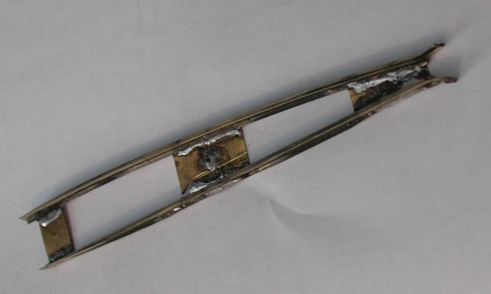
Figure 7: This is a completed MPA
48. Remove spike from switch.
49. Move switch to verify alignment.
50. Remove switch and file down ends where straps and solder extend out. Also file down, round off, frog end, “V” so that it is not an abrupt bump.
51. Place switch back in place and verify alignment.
52. Drill hole in center of strip located at point end of switch.
53. Solder wire under sub-roadbed to brass tube (pivot point), long enough in length to reach the switch motor contacts. (This wire is used to power MPA).
Figure 8: This is a completed closed frog switch.
Install Tortoise switch motor
- Using the MPA to locate where the switch rod is to be mounted to the MPA (points end of the MPA), center the MPA between the rails, mark and drill a location hole in the center of the strap through to the sub-roadbed. Remove MPA and drill a ¼” hole thought the sub-roadbed.
- Using the template from the bottom side, align ¼' hole to template hole (Tortoise Switch motor supplied), identify mounting screw locations and make location bottom side of sub-roadbed.
- Drill 1/32” starter hole for mounting screws.
- Router ¼”hole in sub-roadbed to allow for swing of rod in switch motor to move MPA
- Mount rod in switch motor. Note that if you are using non-standard rod, i.e., larger diameter rod, you will need to drill larger hole in switch motor for mounting rod. Larger wire is used to give more force on MPA.
- Mount switch motor in place with rod placed through hole in MPA.
- Wire up switch motor (including using contact to route power to rails). Follow wire diagram supplied with Tortoise switch motor.
- Drill hole to mount switch (toggle)
- Connect one side of AC transformer to 2 diodes, one forward (+) and one reverse (-).
- Connect (+) to one outer end side terminal of the toggle, connect (-) to the other outer end side terminal of the toggle. (Center terminal should be empty)
- Connect the center terminal of the toggle to a pair of LEDs (red and green connected up in parallel, one forward bias and one reverse bias). This will be used to indicate the direction of the switch.
- Connect the other end of the LEDs to the switch motor drive terminal (#4).
- Connect the other end of the AC transformer to the switch motor drive terminal (#5).
- Test for directional preference.
- Start operating, enjoy.
Your purchase is secure
Satisfaction guaranteed
International shipping
HOME
6 Storeybrooke Drive
Newburyport, MA 01950-3408
Email Doug
888-708-0782 (from US only)
978-465-8798 (International)
Phone calls: 2-5 PM Eastern
Time, Tue-Thu only
Website & Hosting by SovoWeb a division of RedXWebDesign