"Specialists in American Flyer Trains & S-Gauge Railroading"
888-708-0782 (from US only)
978-465-8798 (International)
Phone calls: 2-5 PM Eastern
Time, Tue-Thu only

AM. FLYER REPAIR CLINICS
CLINIC # 10: WIRING AM. FLYER STEAM ENGINES
PART I: GENERAL STEAM-ENGINE WIRING DIAGRAMS---
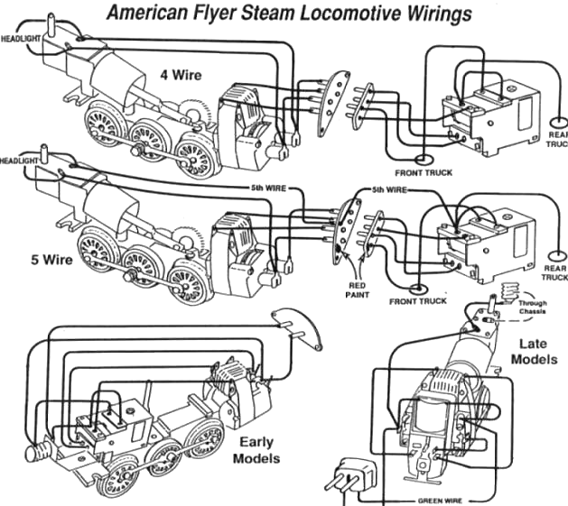
NOTES:
(a) The 5-wire system was used in later locomotives in order to continue to provide power to the light and smoke unit while the engine sat in neutral.
(b) Later five-digit engines which had the two-position reverse unit mounted in the cab on the back of the motor used a two-pin plastic plug to connect the engine to the tender. In most of these engines, the chassis and drawbar are "hot". As a result, it is essential that the two-pin plug be wired as shown. If the two wires are swapped, a short will result when powered on the track, and you may damage the engine. To swap the green and black wires, simply pull the two brass pins straight out of the plastic plug using pliers. Swap the stripped wires, and tap the two pins back into the plug. They should crimp tightly against the stripped wires within the plug.
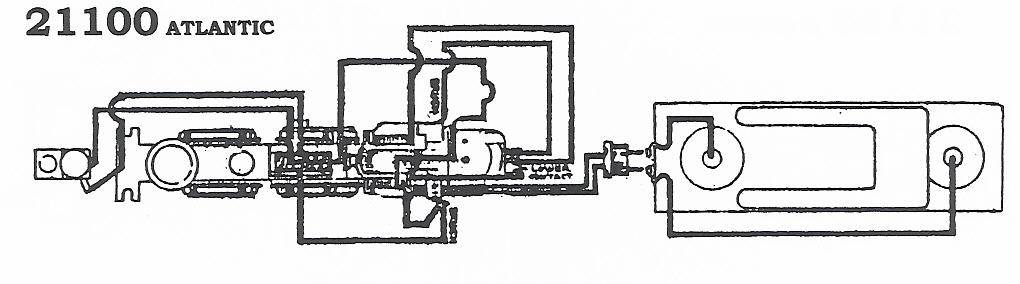
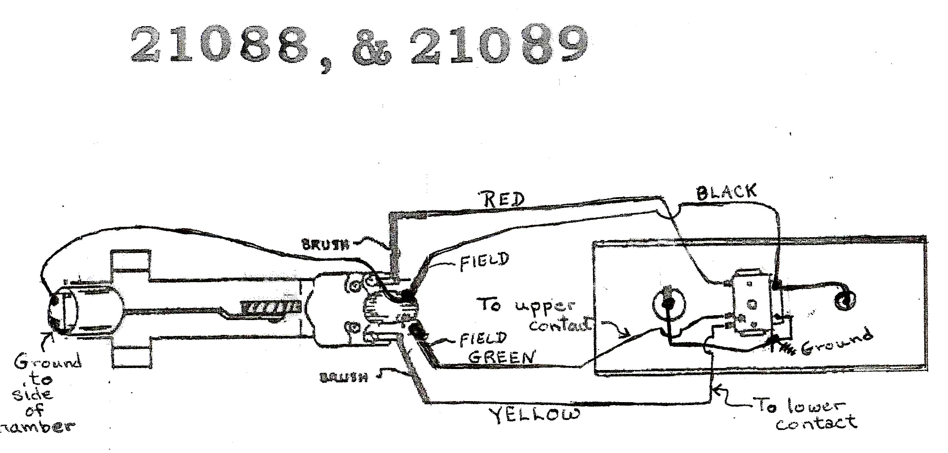
PART II: SPECIFIC ENGINE WIRING DIAGRAMS---
(click image below to enlarge)


Your purchase is secure
Satisfaction guaranteed
International shipping
HOME
6 Storeybrooke Drive
Newburyport, MA 01950-3408
Email Doug
888-708-0782 (from US only)
978-465-8798 (International)
Phone calls: 2-5 PM Eastern
Time, Tue-Thu only
Website & Hosting by SovoWeb a division of RedXWebDesign